FAQ
THz products for NDI and 6G wireless
The photomixer emits THz waves.
The W-type photomixer uses a rectangular waveguide as its output port. Since standard waveguides are used as output ports, W-type photomixers can be easily connected to various components with waveguide interfaces with low loss. On the other hand, as the THz wave frequency increases, the internal dimensions of the output waveguide become smaller and more difficult to manufacture. At present, W-type photomixer products in the frequency band above 400GHz have not been commercialized.
The A-type photomixer (quasi-optical PKG structure) can operate in a high-frequency range. The module emitts a THz wave as a spatial beam through a Si lens installed on the front of the module. By optimizing the Si lens and mounting design, a THz beam with low spherical aberration can be emitted, allowing a single spherical lens to easily produce a collimated THz beam.
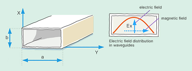
The W type uses a rectangular waveguide as its output port. A rectangular waveguide cannot propagate any THz wave, but can propagate a waveguide whose dimension “a” is less than half the wavelength of the THz wave. This limiting wavelength is the “cutoff wavelength λc” (cutoff frequency fc: fc = c/ λc, c is the speed of light). This is the lower limit frequency of THz waves that can propagate in a waveguide. On the other hand, at 1.5 times the cutoff frequency or higher, the propagation of higher-order modes is more likely to occur, making the propagated THz wave unstable. For this reason, the range of frequencies that should be propagated in a rectangular waveguide is from the cutoff frequency to less than 1.5 times the cutoff frequency.

Waveguide connection flanges for millimeter wave and terahertz bands often use the UG387 flange, a U.S. military standard for 60GHz to 90GHz. As a flange for waveguides in higher frequency bands, UG387/P with an additional knock pin near the waveguide aperture is also used. We use UG387 flanges in all of our W-type photomixers.
As explained in section Q1, the propagation frequency range of a waveguide is from the low-frequency cutoff (fc) to 1.5 times fc or less. It is physically impossible to output frequencies lower than fc. On the other hand, it is possible to output frequencies higher than the upper frequency limit, but this lacks stability due to the tendency to convert to higher-order modes during propagation. Although we cannot guarantee operation above the upper frequency limit, it is possible to use the product with an understanding of the problems associated with higher-order mode conversion.
The electric field of a THz wave propagating in a rectangular waveguide is parallel to the short side of the waveguide. The electric field tangent to the short side is "0" and the center of the long side (on the centerline of the waveguide axis) has a sinusoidal distribution with maximum field strength. In the W-type photomixer, a rectangular waveguide is used as the output port. Therefore, the output THz wave is linearly polarized with the polarization plane parallel to the short side of the output waveguide aperture.

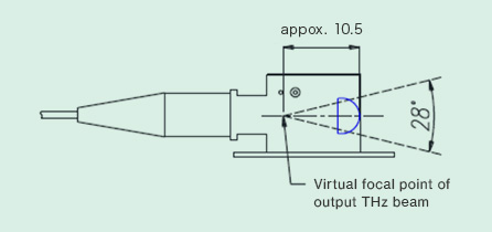
The output THz wave is not a collimated beam. The Si lens used is a hyper-hemispherical lens, and the output THz wave becomes a beam with a spread angle of 28 degrees (NA: 0.24), which minimizes the spherical aberration of the beam. For this reason, a single spherical lens should be placed in front of the module for collimated light.
Beam shape of output Thz wave
Output polarization angle
Due to chip mounting accuracy issues, the optical axes of the hyper-hemispheric lens and the output THz wave are not perfectly aligned. For this reason, we recommend mounting the antenna-integrated photomixer module on a 5-axis fine-motion stage equipped with two gonio stages.
The antenna integrated on the A-type chip is a self-complementary bow-tie antenna. Therefore, the THz wave output from the chip is linearly polarized, and the direction of the polarization plane is shown in the figure below.
Beam shape of output Thz wave
Output polarization angle
By injecting two lightwaves into the photomixer chip, the UTC photomixer converts the optical beat signal into a THz wave with high efficiency. For this purpose, a 1550-nm band light source with two wavelengths is required.The difference in optical frequency between the two light sources should match the frequency of the THz wave to be generated. The optical power of the two light waves should be equal. The maximum total power should be about 60mW and , and it is recommended to prepare an optical attenuator.
A power supply for applying bias to the photomixer is also required. It is recommended to use a source measure unit that can monitor photocurrent.
To avoid burnout of optical connectors, it is recommended to prepare an optical connector cleaner.
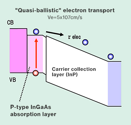
In the UTC photomixer, only electrons are used as carriers traveling in the i-layer (carrier collection layer), and the electrons are moved ballistically to achieve a high-speed response. In the case of excitation at wavelengths other than 1550nm, the THz wave output may be lower than that of 1550nm excitation due to reasons such as the inability to achieve ballistic electron movement in the i-layer. For this reason, 1550nm excitation is recommended.

A source measure unit is recommended to monitor the photocurrent.
The bias circuit of the photomixer has a low-pass characteristic, so it cannot generate a fast modulated THz wave by bias modulation.
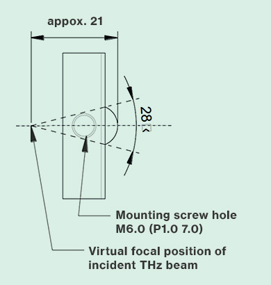
Our quasi-optical FMB diode module uses a hyper-hemispherical Si lens. Please refer to the figure below for the NA and focal point of the incident THz wave.


